GMC Terrain (2010) – fuse box diagram
Year of production: 2010
Engine Compartment Fuse Block
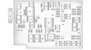
| J-Case Fuses | Usage |
| 1 | Cool Fan 1 |
| 2 | Cool Fan 2 |
| 3 | Rear Defog |
| 4 | Power Windows – Right |
| 5 | Memory Seat Module |
| 6 | Power Seat – Left |
| 7 | Instrument Panel Fuse Block 1 |
| 8 | Instrument Panel Fuse Block 2 |
| 9 | Starter |
| 10 | Brake Booster |
| 11 | Sunroof |
| 12 | Antilock Brake System Pump |
| 13 | Instrument Panel Fuse Block 3 |
| 14 | Power Windows – Left |
| 15 | Antilock Brake System Module |
| Mini Fuses | Usage |
| 16 | Transmission Control Module Battery |
| 17 | Trailer Parking Light |
| 18 | Engine Control Module Battery |
| 19 | Heated Mirror |
| 20 | Trailer Left |
| 21 | Lift Gate Module |
| 22 | Power Lumbar |
| 23 | Trailer Right |
| 24 | Canister Vent |
| 25 | Memory Mirror Module |
| 26 | Regulated Voltage Control Battery Sensor |
| 27 | Rear Accessory Power Outlet |
| 28 | Wiper |
| 29 | Rear Wiper |
| 30 | Air Conditioning Compressor |
| 31 | Rear Latch |
| 32 | Horn |
| 33 | Right High?Beam Headlamp |
| 34 | Left High?Beam Headlamp |
| 35 | Ignition Even Coil |
| 36 | Ignition Odd Coil |
| 37 | Windshield Washer |
| 38 | Front Fog Lamps |
| 39 | Post Catalytic Converter Oxygen Sensor |
| 40 | Engine Control Module |
| 41 | Pre–Catalytic Converter Oxygen Sensor |
| 42 | Transmission Control Module |
| 43 | Mirror |
| 44 | Chassis Control Module Ignition |
| 45 | Spare |
| 46 | Rear Drive Module |
| 47 | Lift Gate Module Logic |
| 48 | Instrument Panel Fuse Block Ignition |
| 49 | Heated Seat – Front |
| 50 | Chassis Control Module |
| 51 | Engine Control Module |
| 52 | Rear Vision Camera |
| Midi Fuse | Usage |
| 53 | Electric Power Steering |
| Micro Relays | Usage |
| 54 | Rear Defogger |
| 55 | Cooling Fan Low |
| 56 | Head Lamp High Beam |
| 57 | Cooling Fan Control |
| 58 | Wiper On/Off Control |
| 59 | Air Conditioning Compressor |
| 60 | Wiper Speed |
| 61 | Fog Lamp |
| 62 | Engine Control |
| 63 | Starter |
| 64 | Run/Crank |
| Mini Relays | Usage |
| 65 | Cooling Fan High |
| 66 | Brake Booster |
Instrument Panel Fuse Block
The instrument panel fuse block is located on the passenger side panel of the center console.
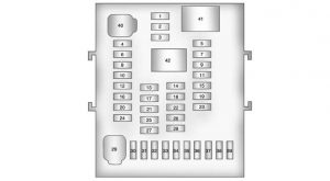
| Mini Fuses | Usage |
| 1 | Steering Wheel DM |
| 2 | Spare |
| 3 | Spare |
| 4 | Body Control Module 1 |
| 5 | Infotainment |
| 6 | Body Control Module 7 |
| 7 | Noise Control Module |
| 8 | Body Control Module 4 |
| 9 | Radio |
| 10 | SEO Battery |
| 11 | Ultrasonic Rear Parking Aid Module |
| 12 | Heater, Ventilation and Air Conditioning Battery |
| 13 | Auxiliary Power Front |
| 14 | Heater, Ventilation and Air Conditioning Ignition |
| 15 | Display |
| 16 | Body Control Module 5 |
| 17 | Auxiliary Power Rear |
| 18 | Instrument Panel Cluster Ignition |
| 19 | PDI Module |
| 20 | Body Control Module 6 |
| 21 | SEO Retained Accessory Power |
| 22 | SDM Ignition |
| 23 | Spare |
| 24 | Spare |
| 25 | PRNDL |
| 26 | Spare |
| 27 | Spare |
| 28 | Spare |
| 30 | Body Control Module 3 |
| 31 | Amplifier |
| 32 | Discrete Logic Ignition Switch |
| 33 | Communications Integration Module |
| 34 | Body Control Module 2 |
| 35 | SDM Battery |
| 36 | Data Link Connection |
| 37 | Instrument Panel Cluster Battery |
| 38 | IOS Module (Passenger Sensing System) |
| 39 | Spare |
| J-Case Fuses | Usage |
| 29 | Front Blower Motor |
| 40 | Body Control Module 8 |
| Relays | Usage |
| 41 | LOG Relay |
| 42 | Retained Accessory Power Relay |
WARNING: Terminal and harness assignments for individual connectors will vary depending on vehicle equipment level, model, and market.
Discussão